DESIGN ASSISTANCE SAMPLE
QUALITY IS IN THE DETAILS
Gear & Shaft CNC Retrofit Services
When you are searching for a supplier to design and manufacture a critical, high-precision gear, shaft, or other part that will perform reliably and safely, you want to know that you and your parts are in good hands. When it comes to the production and CNC retrofit of high quality and cost-effective custom power transmission solutions, there are no better hands than Delta Dynamics Inc.
Delta Dynamics is an ISO 9001 Custom Gear Design Manufacturer, made up of a highly experienced team of professional machinists, engineers, and designers. We provide our customers with “fill-in-the-blank” design and engineering services, assisting each customer from concept to completion. Each part we make conforms to all relevant industry standards, is machined to the highest effective level of precision for CNC retrofitting, and goes through rigorous and detailed inspection and testing at every stage of the production process, from initial design to final delivery.
IF A PICTURE IS WORTH 1000 WORDS, WHAT IS A DRAWING WORTH?
WHAT YOU SEE
Delta Dynamics works with the production of a wide range of parts and systems, often un-proven prototype designs with various levels of complexity, design efficacy and detail. Most often, Delta Dynamics receives a single drawing, from which these parts must be reproduced.
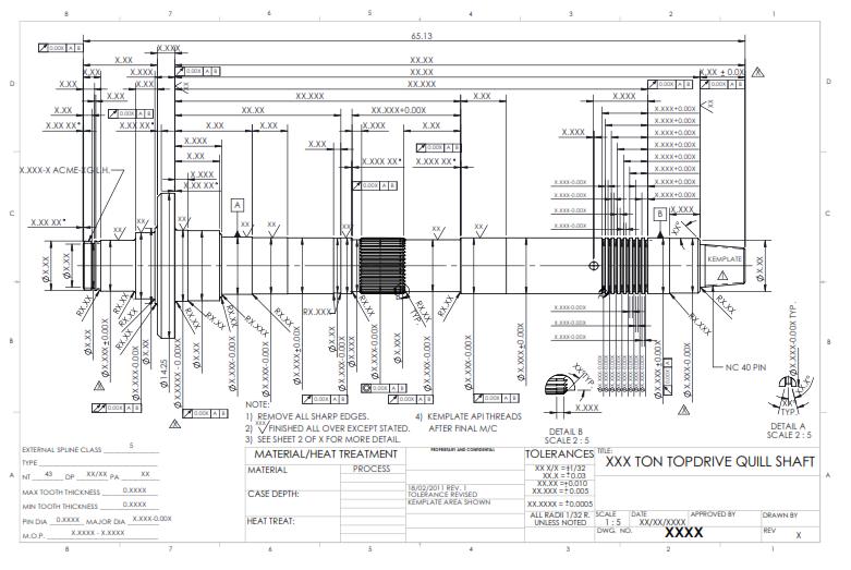
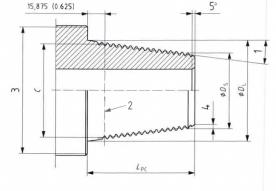
One customer provided us with a basic drawing of a Topdrive Quill Shaft, similar to the one shown below. The drawing included all major dimensions and features, but was incomplete, with some complex components lacking necessary details, such as certain dimensions, tolerances and clearances.
WHAT DELTA DYNAMICS SEES
From the above drawing, Delta Dynamics was able to recreate the quill shaft with exacting precision and detail. Below is an in-depth description of the gear and shaft engineering and CNC retrofitting process carried out by Delta Dynamics. Though this article encompasses the making of only one of these parts, Delta Dynamics has produced many such parts for numerous Oil Industry customers throughout its years of manufacturing and machining work, including hydro static and top drives, gears and reducers, and various shafts.
The reproduction of this elaborate process is aimed at demonstrating to our current and prospective clients the level of precision, the work traceability, the dedication to quality, and the effective application of detailed gear design and manufacturing knowledge that are standard in all of Delta Dynamics’ work.
CONTENT
- INDUSTRY KNOWLEDGE AND BACKGROUND
- "FILL-IN-THE-BLANK" DESIGN COLLABORATION, REVIEW AND REVISION
- GUIDED MATERIAL SELECTION
- MATERIAL TESTING AND VERIFICATION
- INCOMING INSPECTION AND TRACEABILITY
- INCREMENTAL CNC MACHINING OF SHAFT
- CNC MACHINING OPERATIONS
- STRESS RELIEF AND AGING
- IN-PROCESS INSPECTION
- SPLINE CUTTING
- SPLINE INSPECTION
- FINAL MATERIAL TESTING
- PHOSPHATING
- FINAL INSPECTION
- TRACEABILITY PACKAGE
- SHIPPING
- FINAL RESULT
INDUSTRY KNOWLEDGE AND BACKGROUND
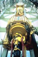
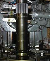
Topdrives are a modern method of drilling oil wells that use one or more electric or hydraulic motors to advance the drillstring. According to Schlumberger’s Oilfield Glossary , “modern topdrives are a major improvement to drilling rig technology and are a large contributor to the ability to drill more difficult extended-reach wellbores.”
The topdrive drilling system, essentially a large drill press, consists of one or more motors which encompass a quill shaft, which acts as the spindle of the topdrive drill and is connected to the drillstring. The quill shaft, a “short section of pipe” which can be over ten feet in length and usually weighs more than 1000lbs, is therefore responsible for transferring torque from the topdrive to the drillstring, and for holding the weight of up to four kilometers of drillstring. The shaft and all of its features must therefore be manufactured to the highest levels of precision and quality, as any failure in the quill shaft can cause catastrophic failure of the whole drill rig system.
“FILL-IN-THE-BLANK” DESIGN COLLABORATION, REVIEW AND REVISION
Upon receiving the Production Order for a part, Delta Dynamics immediately goes to work, determining all applicable industry standards and checking all the dimensions and specifications for conformance to these standards. This requires numerous calculations to determine geometrical dimensions and tolerances.
All quill shaft dimensions are checked against a part sample, adjusted for clearance and effective machining where necessary, and given tolerances where none were included.
Generation of Spline Details and Design
A detailed design of the shaft’s spline is produced using advanced gear design knowledge and software.
The original spline drawing specified:
- Spline Class
- Spline Type
- Number of Teeth
- Diametral Pitch
- Pressure Angle
- Major and Minor Diameters
Delta Dynamics’ final design is described by a 5 page, 300-line report that contains over 120 dimensions, values and factors, including:
- Over 75 dimensions for both the Shaft and Hub splines, with each dimension
conforming to ISO and ANSI standards, having upper and lower tolerances
and clearance, and including Nominal, Actual and Effective dimensions
for spline manufacture.
- Spline Pitch
- Circular Pitch
- Internal and External Major and Minor Diameters
- Tooth Thickness
- Normal Module
- Face width
- Addendum and Dedendum coefficients
- Tip and Root Radius Factors
- Over 50 more
- Over 50 values for material properties, strength calculations and safety
factors
- Shaft and Hub materials
- Heat Treatment processes
- Conformance standards
- Maximal Circumferential Force
- Participation Factors
- Maximum Torque
- Pressure Stress
- Minimal Safety Factors
- And more
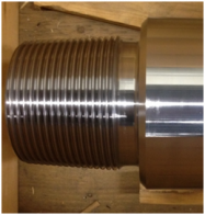
Design of API Threaded Rotary Shoulder Connection
On the drawing provided, one end of the shaft was shown simply as a tapered cylinder with no dimensions, labeled only as “NC40 Pin”. This refers to a specific API Rotary Shouldered Thread Connector, used in many different rotary drilling rigs in the Petroleum and Gas Industries. While the customer writes simply “NC40 Pin”, what Delta Dynamics sees is a highly complex tapered thread, whose dimensions and design are rigorously controlled, and which requires special certification and licensing to manufacture and inspect – certification and training which Delta Dynamics has.
Conformance to API Threading Specification
The threads of Threaded Rotary Shouldered Connections, which are used to connect one element of a drillstring or topdrive to another, must be capable of withstanding the force required to advance and retract over 4 kilometers of drillstring. The load must be perfectly dispersed across all threads of each connection for maximum thread contact between pin and box, as otherwise a thread may break causing catastrophic failure. To achieve this, an extremely high level of precision is required in the pitch, taper, angle and other elements of the threads.
The API/ISO Specification for Threading and Gauging Rotary Shouldered Connections (API 7-2/ISO 10424-2) is a 102 page document which must be possessed by, and who’s every detail must be well known by, all API thread manufacturers. The Specification delineates all procedures and required dimensions for manufacturing, treating and inspecting API threads, and for the manufacture, maintenance and use of API Master, Reference and Working gauges.
The Specification includes:
- Over 40 fundamental dimensions for over 20 styles of API threaded pins and
boxes (male and female connections), each with strict, thousandths-of-an-inch
tolerances;
- Thread taper
- Pitch diameter at gauge point
- Pin and Box Thread Depth
- Thread Lead
- Half Angle
- Root Radius
- Over 30 more
Along with many other dimensions and instructions related to specific applications.
- Over 30 dimensions for thread gauges;
- Taper
- Compensated thread length
- Thread heights
- Gauge root and crest truncation
- Major and minor reference diameters
- Gauge stand-off
- Plug and Ring gauge length
- Over 20 more
- Over 30 gauges dimension tolerances, for regional and grand master gauges, master gauges, and working gauges
- Detailed guidance for all related procedures, including:
- Heat treatment
- Cold working
- Stress relief
- Benchmarking
- Break-in
- Gauge maintenance, calibration and use
- Torque-hammer methods and weights
- Gauge certification
- and more
Design Finalization and Consultation
Each detail of the design is discussed and consulted upon to insure that the final design is exactly what the customer needs. Material choice, as well as all heat treatment and stress relief procedures, are verified and recorded for part traceability. After all the dimensions, tolerances and features of the design have been calculated, or determined from industry specifications, and have been verified to conform to all industry standards and Delta Dynamics’ own Quality Management Procedure stipulations, manufacturing can begin.
- Every detail is checked against industry standards
- All procedures finalized
- Treatments and Testing planned and scheduled
GUIDED MATERIAL SELECTION
Through consultation between Delta Dynamics and the customer, forged 4330v Modified Steel is selected as the most suitable material for producing the quill shaft. This material has the ductility, tensile strength, cold-temperature impact resistance, and other material properties required for the demanding conditions of northern-latitude oil rig drilling.
Forging is the optimal metalworking process for the production of the shaft blanks due to the unique benefits it offers. These benefits include:
- Fine grain wrought structure
- High ductility and impact resistance
- Homogeneous density
- Low porosity
- Increased directional (axial) strength
- Cost efficiency
The shafts are open-die forged from cast ingots to a shape that requires minimal machining, allowing maximum retention of the forging’s material properties. The shafts are normalized, quenched and tempered to enhance these material properties.
MATERIAL TESTING AND VERIFICATION
Before being sent to Delta Dynamics, the shafts are thoroughly tested and analyzed for chemical and mechanical properties by the forge. Samples of the material are taken from the forged shaft and subjected to destructive testing, while the shafts themselves are subjected to rigorous non-destructive testing.
Three detailed test reports are generated, and given to Delta Dynamics upon delivery of the shafts, to guarantee material quality and ensure full part traceability:
- Certified Material Test Report
- Magnetic Particle Examination Report
- Ultrasonic Examination Report.
Certified Material Test Report
The Material Test Report details the material specifications, and the results of chemical analyses and destructive testing performed on material samples. The report includes:
- Full Material Specifications
- Part Description
- Heat Treatment Processes with Load Numbers
- Chemical Analysis
- Mill Data detailing material composition percentage for 13 elements, up to 3 significant figures (0.00X %)
- Product Analysis detailing material composition percentage for 10 elements, up to 3 sig. figures (0.00X %)
- Mechanical Properties – Longitudinal Tensile Test
- Yield Strength
- Ultimate Tensile Strength
- Elongation percentag
- Reduction of Area percentage
- Offset
- Mechanical Properties – Transverse Tensile Test
- Yield Strength
- Ultimate Tensile Strength
- Elongation percentag
- Reduction of Area percentage
- Offset
- Charpy V Notch Impact Test – Longitudinal at -4 F & -40 F
- Impact Test
- Lateral Expansion
- Shear Fracture
- Grain Size
- Brinell Hardness
- Reduction Ratio
Magnetic Particle Inspection
Magnetic Particle Inspection (MPI) is a non-destructive test designed to detect surface and slightly subsurface material discontinuities, such as cracks.
The part is magnetized, and then ferrous metal particles (magnaflux) are applied to the magnetized surface. Where there is a crack or discontinuity, the ferrous particles will be attracted due to magnetic flux leak, making the crack visible.
The MPE report is highly detailed, including:
- Procedure Specification (API 8C)
- Descriptions of all equipment
- Serial numbers
- Calibration date
- Date of next calibration
- Amps, Current, and Magnetic Field
- Magnaflux Concentration and Type
- Lighting Intensity
- Part Surface Finish
- Part De-magged Gauss Level (magnetic flux density)
- Quantity Tested
- Quantity Accepted
- Technician Qualifications
- Technician Certification
- Technician Eye Examination Report
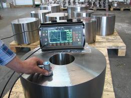
Ultrasonic Examination
Ultrasonic Examinations use high-intensity, ultrasonic sound waves to detect internal material flaws. Flaws in the material create an “echo” which allows their depth, location and size to be determined.
This test is also used to characterize the material and confirm uniform density and porosity.
The Ultrasonic Examination Report includes:
- Procedure Specification (API 8C)
- Descriptions of all equipment
- Calibration blocks
- Transducer Angle, size, Serial # and MHz
- Calibration settings
- Diagnostic unit make, model, Serial #, calibration start and end date
- Couplant type
- Part Surface Finish
- Quantity Tested
- Quantity Accepted
- Technician Qualifications
- Technician Certification
- Technician Eye Examination Report
The Specification includes:
- Over 40 fundamental dimensions for over 20 styles of API threaded pins
and boxes (male and female connections), each with strict, thousandths-of-an-inch
tolerances;
- Thread taper
- Pitch diameter at gauge point
- Pin and Box Thread Depth
- Thread Lead
- Half Angle
- Root Radius
- Over 30 more
Along with many other dimensions and instructions related to specific applications.
- Over 30 dimensions for thread gauges;
- Taper
- Compensated thread length
- Thread heights
- Gauge root and crest truncation
- Major and minor reference diameters
- Gauge stand-off
- Plug and Ring gauge length
- Over 20 more
- Over 30 gauges dimension tolerances, for regional and grand master gauges, master gauges, and working gauges
- Detailed guidance for all related procedures, including:
- Heat treatment
- Cold working
- Stress relief
- Benchmarking
- Break-in
- Gauge maintenance, calibration and use
- Torque-hammer methods and weights
- Gauge certification
- and more
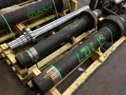
INCOMING INSPECTION AND TRACEABILITY
The forged shafts are then sent to Delta Dynamics, along with all generated documentation, including material certifications and test reports.
Delta Dynamics maintains traceability on all incoming, outgoing, and in-process materials and parts.
When the forging is received, it is immediately recorded in the Forging Receiving Log, which tracks all details of the material, including:
- Purchase Order (PO) #
- Delta Dynamics’ Job #
- Part #
- Piece #
- Heat Treatment (HT) #
- Unique Forging (UF) #
The PO#, Job #, Part # and quantity are verified to match the PO, and then the forgings are checked carefully for:
- Damage
- Deterioration
- Spoilage
Each forging is then marked with the HT #, UF #, Part #, and DDI Serial #, if not already done by the forge. The part is put in Holding, apart from the production floor, until the initial inspection is complete.
The job Traveler, along with all certificates and test reports, are submitted to the Quality Assurance Representative (QAR) or Inspector, who verify that all material properties and test results match the design, PO and drawing specifications.
The material certificates and test reports are stamped with the Job #, Part # and PO#, signed and dated by the inspector, and added to the job file
The inspector records the Serial #, HT# and UF# on the shop Traveler, dates and signs it, and then submits it to the Shop Superintendant to start production of the part.
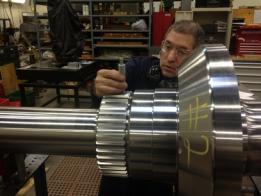
INCREMENTAL CNC MACHINING OF SHAFT
The quill shaft has a highly complex and customized shape, having numerous features including:
- NC40 Pin
- ACME Thread
- Large Diameter Flange
- Chamfered Bore
- Spline
- Load Distribution Grooves
- Over 30 different shaft diameters
- Numerous fillets and chamfers
RED-SEAL Machining Certification

These high-precision features allow no room for error in their manufacture. Skilled machinists operating high-precision, powerful machining systems are necessary for the production of such large, complex parts as a topdrive quill shaft.
Nearly all of Delta Dynamics' machinists, inspectors and production staff members are Red-Seal Certified Journeyman Machinists. Red-Seal is an interprovincial Standards Program that maintains a standard of excellence for skilled trades in Canada. Machinists with Red Seal Certification have each completed four levels of technical training, along with minimum four years of on-the-job experience as an apprentice.
Delta Dynamics runs numerous Computer Numeric Controlled (CNC) milling, turning and boring centers, several manual lathes, and over 15 manual gearing centers. Please see our Capabilities page for more details.
- Red-Seal sets a standard of excellence for Canadian Trades
- Nearly all Delta Dynamics' design and production staff are Red-Seal Certified Journeyman Machinists
- Each Machinist has four years of technical training and a minimum four years of experience
CNC MACHINING OPERATIONS
CNC retrofit technology is used to create these high-precision features. Each dimension of the shaft is machined in three: Roughing, Semi-Finish, and Finish. This incremental machining method allows tight control of final part dimensions, and is essential to the reduction of chatter and surface stress.
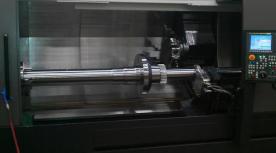
The CNC machining of the shaft is carried out in several separate operations. CNC retrofit technology is used so that precise measurements can be taken. For this particular part, three operations are carried out.
OPERATION 1
The first CNC machining operation consists of 5 separate processes, each roughing out a different major dimension or face of the shaft:
- Shaft faced and centered
- First Bore End chamfered
- Flange Outside Diameter and faces roughed
- Shaft length roughed
OPERATION 2
The second operation consists of 17 processes: 7 Roughing, 4 Semi-Finishing, and 6 Finishing
In this operation, the following features are machined:
- Second Bore End chamfered
- Flange OD and faces finished
- ACME Thread
- 4 shaft diameters finished
OPERATION 3
The third and final CNC operation consists of over 60 processes: 2 Roughing, 31 Semi-Finishing, and 28 Finishing.
In this operation the following features are completed:
- NC40 Pin Connector
- Spline Major Diameter
- 17 shaft diameters
- 8 Load Distribution Grooves
In total, forty-two pages of CNC programming code were used to produce the numerous features of the shaft, with diameters ranging from 4” to 14.25”, and features as small as 0.04” fillets.
STRESS RELIEF AND AGING
Between the roughing and finishing processes in the second and third operations, the shaft is returned to its pallet and left for a number of days. This is to allow tensile and compressive residual stresses from the rough machining processes to be released. Residual stresses in the material can cause warping, resulting in out-of-tolerance final dimensions.
Also, in between certain major processes the chuck and tailstock may be loosened to allow for tension and torsion, built-up during cutting, to be released. This yields higher accuracy results in subsequent processes.
The first CNC machining operation consists of 5 separate processes, each roughing out a different major dimension or face of the shaft:
- Shaft faced and centered
- First Bore End chamfered
- Flange Outside Diameter and faces roughed
- Shaft length roughed
IN-PROCESS INSPECTION
After all CNC machining operations are completed, the shaft, along with the traveler, was passed off to the Inspector for inspection. Each dimension of the shaft is inspected and measured to ensure conformance to specifications and drawings.
Each measured dimension is recorded for traceability in a Delta Dynamics Inspection Report, with a total of 125 dimensions being inspected:
- 32 Shaft Diameters
- 15 Fillet Radii
- 54 Axial lengths
- 10 Angles
- 14 Total, Circular and Concentricity Runout Tolerances
Surface finishes of ten faces of the shafts are also confirmed to match the required specifications.
The NC40 Pin is then inspected separately and an API Thread Inspection Report was generated which includes:
- Pin Connection Specification Numbers
- Thread Drawing Reference #
- Part Serial # and description
- Thread Profile check
- 11 Dimensions, each with:
- Design Value
- Tolerance
- Actual Measurement
- Model #, Serial # and Setting Standard of each Gauge used
Both Inspection Reports, along with the Shop Traveler, are signed, dated and stamped by the Inspector. The reports are added to the job file, while the Traveler and the shaft are passed on to the Manual Machining Supervisor for the next stage in the production process.
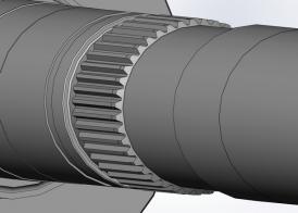
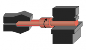
SPLINE CUTTING
The spline shaft is produced on a hobbing machine. As described above, the spline is a highly detailed feature of the design, requiring a high level of precision in its manufacture.
The process of hobbing, in which both cutting tool and work piece are rotating, is uniquely effective at the production of well-formed involute profiles of varied pressure angles and pitch diameters using the same cutter. The process of hobbing is unique to precision gear manufacturers, and cannot be done by the average machine shop.
The spline has an involute profile, designed to create maximum contact area with the mating hub spline. It was designed to high tolerances, with a backlash of only 0.003”.
- Spline shaft hobbed
- Hobbing generates superior involute-profile gear and spline teeth
- Hobbing process and equipment are unique to gear manufacturers
SPLINE INSPECTION
After all machining is completed the shaft is cleaned, deburred, and stamped with the serial number, part number, material specifications and customer job number.
The spline is then inspected for conformance to design and specifications, with over 10 dimensions being measured or determined, including:
- Pressure Angle
- Tooth Thickness
- Backlash
- Pin Diameter
- Major Diameter
The Job Traveler is signed, dated and stamped by the Inspector as approved.
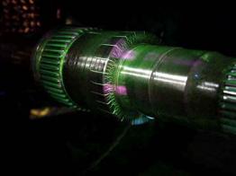
FINAL MATERIAL TESTING
With the machining and gearing processes complete, the shaft is once again tested for material integrity through non-destructive testing (NDT).
The shaft is tested via Magnetic Particle Inspection to confirm that no surface or sub-surface cracks had formed during the manufacturing processes.
Having passed the MPI test, the MPI Report, containing all the details and information described above, is added to the project file.
PHOSPHATING
The final process in this complex job is to have the threaded connector (NC40 Pin) phosphated. Phosphating, also known as Parkerizing, is a heat treatment method that creates a phosphate conversion coating on a metal surface that protects it from wear and corrosion. The metal part is submerged in a phosphoric acid solution of zinc or manganese, and varying amounts of other ingredients such as nitrates and chlorates, which is raised to a temperature of 88-99°C. The phosphoric acid and metal react, causing zinc or manganese phosphates to fall out of solution and be deposited on the metal surface. This produces a light-, medium- or dark-grey finish on the metal part, depending on the ingredients of the phoshating solution.
The phosphated surface is then coated or painted with an oil or sealer to complete the protective coating. The Phosphate and Oil (P&O) coating effectively protects the part’s surface from wear, corrosion and galling, all of which are major concerns with a quill shaft thread, which is attached to and detached from drillstring sections thousands of times in its lifetime.
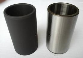
- Phosphating creates a light- to dark-grey surface coating on parts
- Coating protects phosphated surfaces from wear, corrosion and galling
- Increases lifetime of part
FINAL INSPECTION
The shaft is then given a final inspection to ensure conformance with all drawings and specifications, with all 125 shaft dimensions – along with over 10 dimensions for the spline and 11 dimensions for the API thread – being checked
The API NC40 Pin thread is then stamped with Delta Dynamics’ unique Monogram, which includes:
- Manufacturer Identification
- Specification
- Threading Date
- Size and Style of threaded connection
The job Traveler is again signed, dated and stamped by the Inspector or QAR to confirm the shaft has passed inspection, and the Traveler and all inspection reports are added to the job file and passed over to the QAR.
TRACEABILITY PACKAGE
The QAR prepares a traceability package for submission to the customer along with the part. The standard Traceability package includes:
- DDI Conformance Certificate
- DDI Traceability Report
- DDI Dimensional Inspection Reports
- DDI Gear Test Report
- Material Certificates
- Material Test Reports
- Customer Traceability Report
SHIPPING
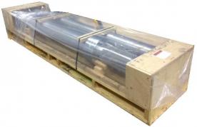
The shaft, having been signed off as having passed all inspections and meeting all specifications and requirements, is wrapped in a protective cover to prevent damage to the spline, API thread, ACME thread and all other features. Then, along with the full traceability package, the shaft is packed in a crate built of certified bug- and disease-free wood that can cross international borders without concern, and is shipped directly to the customer via third-party shipping.
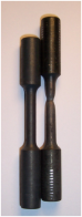
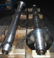
FINAL RESULT
The final product is an extremely precise, well-designed and fully functional Quill Shaft that is capable of withstanding all the rigors of advancing and retracting over 4 kilometers of drillstring on oil rigs in northern Canadian climates.
Throughout each step of the manufacturing process, from the initial design to the final tests and treatments, from the material forging to the machining and inspection of the shaft, Delta Dynamics uses its extensive gear and power transmission systems design and manufacturing experience to ensure that the end result exceeds the customer’s expectations and requirements.
Each stage of the month’s long project is carefully and rigorously tracked and recorded by Delta Dynamics, producing over forty pages of documentation that demonstrate full traceability of the part, insuring that the shaft is fully guaranteed to perform as intended, or better.
- High-precision, top quality parts
- Every process and step is planned, completed and tracked with rigorous attention to detail
- Parts meet or exceed all specifications, standards and expectations
- Guaranteed to perform as desired